|
 |
|
|
|
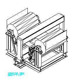
| The above picture shows a mount I designed to be mounted on a steering assembly. The box frame and the two big rolls are part of the steering assembly, while the part that is added to the side is the new assembly. It was decided that a motor and gear reducer was wanted for improved operations. The problem was to design a mount to hold the motor & gear reducer that didn't weight too much. The weight of the new mount along with the motor and reducer is about1300 lbs. The deflection at the end of the beam should be less than 0.05 inch. It could have been designed lighter however, policy dictates that it should be made to last. |
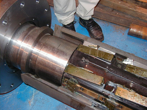
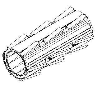
| In the above picture is part of a mandrel assembly, which is used to hold rolls of steel in place as it is wound up after it is heat treated in a furnace. A belt rapper is used to begin winding the steel on the outer part mandrel. The sleeve which I drew is the part in the lower right corner with the ramped surfaces. Using hydraulics, the sleeve is extended, causing the outer surfaces to retract so that the roll of steel can be removed from the mandrel. I used 3 2D drawings to complete the 3D drawing below of the sleeve. The problem encountered with the sleeve, is that it was wearing where it contacted the main shaft. With input from others, I modified the sleeve to accept a replaceable wear ring where it made contact with the main shaft. |
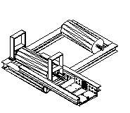
| When rolls of steel are galvanized the gauge of the coating needs to be checked. Below is a drawing I completed of the frame with the steel coming down from above, traveling around a roller to change directions 90 degrees before going through the sensor. It then changes directions 90 degrees again. I drew the existing assembly from 2D drawings and then designed a guard for the sensor to prevent wrinkles in the steel damaging the sensor. Most of the original ideas had been completed before I was assigned this project however, I did draw the entire assembly in 3D and further refined the design. |